


Need 10 or more boards? Contact us for wholesale pricing!
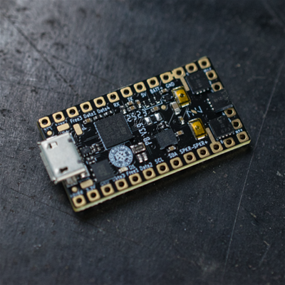
The latest fully open source Saber soundcard with Smoothswing and Pixel capability! An advanced board with a tremendous amount of customization options.
Preloaded default sound package is installed on the included Sandisk Ultra Micro SD Card
- 80Mhz ARM processor
- 160kb RAM
- 512kb Flash
- 3 button pads (capacitive touch capable)
- 4 neopixel data pads
- 3 use for anything pads (These can either be used to drive 20mA LEDs directly, or as neopixel data pads, button pads or servos)
- 3 serial ports
- 3 i2c ports
- 2 SPI ports
- 6 FETs
- 6-axis motion chip
- 3-watt amplifier (mono)
- S/PDIF or I2S output
- 450mA USB charging
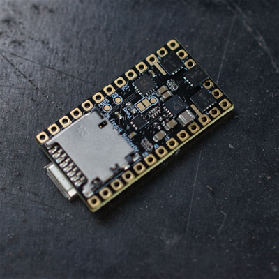
- SDIO sd card reader
- onboard status LED
- center-board pads for: USB, SWDIO and additional 3.3v capacitor
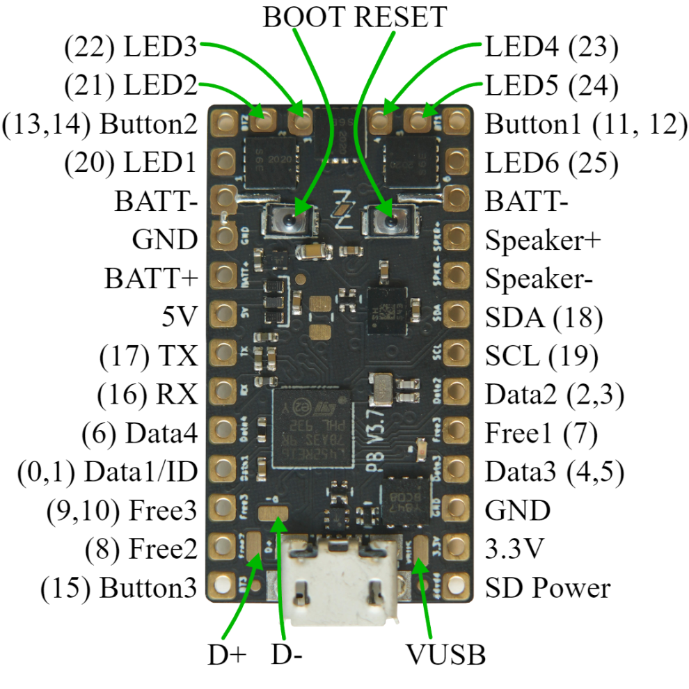
Technical Specs
- BATT+ - 2.6 to 5 volt input, drives everything except the LEDs
- BATT- - negative pad for LEDs, needs to be at same level as GND when both are connected. Note that there are two of them, which can be useful when driving many powerful LEDs.
- GND - ground for electronics except LEDs. Note that the two GND pads are interchangable and connected through the board.
- Button 1/2/3 - Hook up to closing buttons, or potentially touch buttons.
- Data 1 / ID - Normally used to measure the blade ID restor, and if it's a neopixel blade, feed out neopixel data. For a fixed non-neopixel saber, it could be repurposed. Note that this pin has an internal 470 ohm resistor on it, so when hooked up to a neopixel blade, it does not need any resistors.
- Data 2-4 - additional neopixel data outputs, or free for other purposes.
- Free 1-3 - Can be used as buttons, additional neopixel outputs, pwm or servos
- LED 1-6 - Hooks up to negative side of LED (positive side of LED hooks up directly to battery.) These pads can handle up to 30 volts.
- SD Power - FET-controlled 3.3v. can be used to power down bluetooth and displays in low-power mode.
- SDA, SCL - i2c bus, used internall to talk to the motion sensing chip.
- 5v - generated by the proffieboard, normally it's only on when sound is playing.
- 3.3v - generated by the proffieboard.
- GPIO - (general purpose in-out) all gpio pins can be used as neopixel ouputs, button inputs, IR reading inputs and many other purposes.
- PWM - (pulse-width modutlation) pwm-capable pads can be used to drive LEDs and servoes. The PWM can control the brightness of the LED or the angle of the servo.
- Analog - analog-capable pins can use analogRead() to read voltages between 0 and 3.3v volts. (Voltages outside this range may damage the board.)
- Serial - simple serial ports for talking to other chips.
- i2c, SPI - buses for talking to other chips.
- S/PDIF, I2S - audio output options
- Wakeup - deep-sleep wakeup capable pins
- DAC - digital-to-analog capable pins
- IR - ir output pin
Want to mess with the board settings? Check out the ProffieConfig All-In-One Proffieboard Management Utility.
Installation
- Please test the boards first. Plug it in to a computer and make sure it works and that the SD card can be accessed. Go to the ProffieOS page and make sure you have Arduino and your computer configured correctly for programming the board.
- Use the configuration generator to work out the wiring and the configuration. Please note that the configurator can only generate a small fraction of all possible configurations, but if you don't use the configurator you will need to construct your own config file, which can be more difficult.
- Solder the board according to the wiring diagram in the configuration generator. Make sure to check all your soldering with a multimeter. Take the SD card out before soldering.
A note on reverse polarity protection
This version of the proffieboard has reverse polarity protection. Please note that there are two major caveats to the reverse polarity protection:
- It does not protect whatever is hooked up to LED1-6
- It does not work while charging!
Regular LEDs don't have a problem with reverse power, but neopixels can easily fry if the battery is hooked up backwards. Some pixels, like WS2813 have their own reverse polarity protection which is required if you really want your saber to survive unharmed if you plug in the battery backwards.
Wire gauges
Most pads on the proffieboard will not need to carry any significant amount of power and can use 30 awg (very thin) wire if you choose. However, Battery- will carry the combined power of all your LEDs, which is a fair amount of power. It is recommended to use thicker wires, for these wires. There is no absolute rules for what wire guages are required, but here is a helpful chart. (See the "chassis wiring" column.) Keeping the high-power wires short helps as well.
Programming
Most of the time, programming the Proffieboard is as easy as hookin up the USB cable to a computer and pressing the "upload" button in the Arduino IDE. However, an interrupted upload or a crashing program can sometimes stop that from working. If that happens, hold the boot button, then press and release the reset button. This will put the Proffieboard in bootloader mode, and pressing "upload" should now work.
Touch Buttons
Any of the buttons can replaced with a touch button. To wire a touch button, simply hook up the corresponding wire to a metal surface. Note that in spite of the name, you don't actually want anybody to actuall touch the touch buttons. The metal surface needs to be insulated, both from the rest of the hilt, and from the fingers that will be "touching" it. In my case, I used a circuit-board clamp card in a Graflex lightsaber, then I covered it up with tape to insulate it from everything else. More details here.
Choosing Resistors
Calculating resistor values is fairly easy. Just look up how many amps the LED can handle and at what voltage it expects to achive that current. Then the resitor value we want is (BatteryVoltage - LedVoltage) / LedAmps. And the resistor needs to handle (BatteryVoltage - LedVoltage) * LedAmps watts. Example, if the LED wants 1A @ 3.2 volts, the resistor would be (3.7 - 3.2)/1 = 0.5 ohms, (3.7 - 3.2) * 1 = 0.5 watts.
Note that I use 3.7 volts for the battery in these calculations, while li-ion batteries tends to top out at 4.2 volts. Proffieboard can compensate for this by using PWM to reduce the total amount of power and heat generated by the LED when the voltage is higher than what it is rated for. This mode is efficient and seems to work well, but it is possible that it will reduce the life of the LEDs. If you are not comfortable with this, you should use 4.1 or 4.2 volts in the calculations above.
Multi-battery setup
The FETs on the proffieboard can handle voltages up to 30v, so it's possible to do multi-cell setups. However, "Battery+" cannnot handle more than ~4.5 volts. So you would need a separate battery to power the CPU. Another possibility would be to do two batteries in series, but only use one of them to power the CPU. Since the batteries would be discharged unevently, they would have to be charged separately. In the future, I hope to make "Battery+" handle a wider range of voltages, which would make multi-cell configurations a lot simpler.
Using Data 2, Data 4, RX and TX for PWM
Data 2, Data 4 and RX and TX can be used to drive LEDs instead of neopixels or serial ports. However, a single timer is used to drive these pins. For PWM, the timer is usually set to 800Hz, however, when neopixels are used, this timer is set to 800kHz. This basically means that if you use any neopixels, all of these pins become unsuitable for driving LEDs. So, if you select a 6-segment blade + flash string in the configurator above, you cannot use the other data pins to drive nepixels unfortunately.
Troubleshooting
If you're having problems, check out the troubleshooting page.
Problems? Questions? Suggestions? Check out The Crucible.
Due to the advanced nature of the board for programming, it can take a bit of time to learn and it is highly recommended that you review the below links before proceeding.
Fett263 Getting Started
fredrik.hubbe.net
Fett263 Homepage


It's a proffie board so you won't be disappointed
Not much different than the former version from just looking at it. That said the changes are there once you get it running. The most noticable changes in my opinion are sound quality, overall response & price.
Nice sound board
The proffieboard v3 is nice, I like that this sound board has a faster SD card reader and that the v3 is not that different when it comes to where to solder wires allowing me to use the muscle memory of the older version. I also like the way it was packaged I like the little box with 3d printed cut-out it came in.